| General Information |
| Application |
| Sample Loading |
| Cleaning the Geometry |
| Equations |
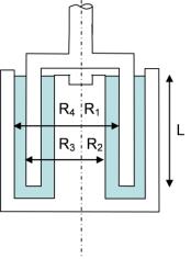
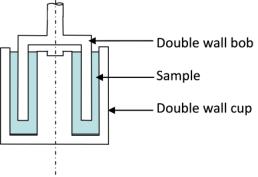
The double wall concentric cylinder geometry is used for testing lower viscosity fluids that generate very low torques when tested with parallel plates or a cone and plate. The double wall concentric cylinder is also used instead of the standard concentric cylinders when only small sample volumes are available. The schematic of a double wall concentric cylinder is shown below. The double wall cup and bob differ from the standard concentric cylinders in that the bob is uncapped and hollow, and the cup has an inner and outer wall.
There are two annular gaps. The torque generated in the double wall concentric cylinder is approximately double of the torque generate in a single concentric cylinder with the same dimensions. The inner gap of the double wall concentric cylinder is slightly smaller than the outer, such as the average shear rate in both gaps is the same.
The nominal sample volume is approximately 8 mL to 9 mL. In all cases, the fluid level must be at least up to the sample fill level "lip". To avoid edge and boundary layer errors, filling slightly past the lip is desirable. Overfilling, however, especially in the case of higher viscosity fluids, may result in errors due to an actual wetted bob length longer than the entered effective length.
The double wall concentric cylinder is typically used on very low-viscosity fluids and when a limited sample volume is available. The sample volume required is approximately 3 to 4 times lower than required for a single concentric cylinder system of similar size.
The double wall concentric cylinder for the AR Rheometer can be combined with the Peltier concentric cylinder jacket.
To facilitate cleaning of the geometry, the inner cup can be removed from the outer cup. Unscrew the inner cup mounting screw and remove the inner cup and O-ring . Clean the cup as necessary. Reassemble the lower geometry (cup) by installing the inner cup into the outer cup using the inner cup mounting screw. Before reassembling the geometry, inspect the O-ring for cuts or other damage, and replace it if necessary.
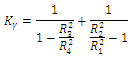
Strain Constant |
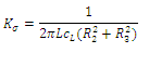
Stress Constant |
|
|
|
VariablesL = Length of cylinder (m) CL = Face factor R1, R2, R3, R4 equal the following radii (m):
|
|